Module 2 - Fuel System
Module 2 Build:
<15th September 2005>
 Fuel Pump:
The Fuel pump i have is not the same as the one in the diagram. The one from the build manual is for a carburetor engine, mine will be fuel injection throttle bodies and so requires a different fuel setup. I will need to connect the fuel pump to the bottom most outlet in the fuel tank for the "IN" supply. The "OUT" end will then connect to a rubber fuel hose that will lead down to a fuel filter. This is turn will feed into the solid fuel pipe that will run next to the brake pipe under the underside of the car under the driver.
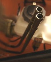
 Then at the front of the car the solid pipe comes up near the master cylinder. This pipe connects to throttle bodies fuel rail which is kept at a high pressure from the fuel pump at the rear. There will be a fuel pressure regulator at the other end of the fuel rail that will maintain the pressure in the fuel rail but will reduce the pressure right down and pass the excess fuel through a rubber hose to a second solid fuel pipe that runs alongside the first one, back to the rear of the car where this excess fuel is put back into the fuel tank.
 <16th September 2005>
The first job with the fuel system is the bending and fitting of the solid fuel pipes. I've been putting this off as although the brake pipe bending went ok, these are much bigger pipe and in turn will be harder to bend without kinking. I toyed with the idea of getting a small pipe bending tool for these but decided to adopt the same approach as with the brake pipe just slower!
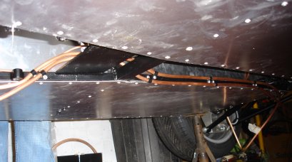
As mentioned earlier there will be two solid pipes running the underside of the car. They will come out between the throttle cable and the master cylinder at the front and in front of the rear right hand wishbone at the back. I marked to 2 places to bend with masking take and started to gradually work it around a pipe about 4 inches diameter. It all went well but afterward i noticed it had flattened on the bend ever so slightly. I don't think it will make any difference as blowing through the pipe gives no more resistance then the straight pipe. However i will adopt a different approach for the other bends. For this i used a roller stand that would normally be used for supporting wood and allowing it to move in one direction. This worked extremely well and the bend produced with this approach were perfect and uniform.
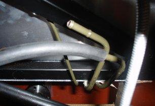
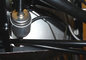
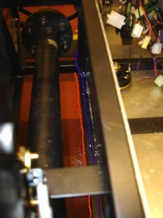
So as you can see in the pictures i now have the two pipes P-Clipped and riveted to the chassis on the underside, with a neat bend each end just waiting for the rubber fuel hoses to be attached.
I know need to decide where to attach the fuel pump and fuel filter. So i placed the fuel tank where it will end up so i could work out the route for the rubber pipes. As you can see from the picture below the output from the fuel tank is quite low. So from this i think i will place the fuel pump connected to the chassis rail that has the diff stabiliser on it probably just to the left of that bracket. This will mean just a few inches of pipe between the tank and the pump, it will also give me a wider range of options for locating the fuel filter.
<9th October 2005>
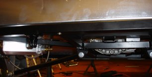
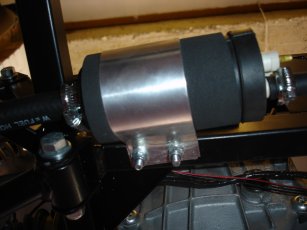
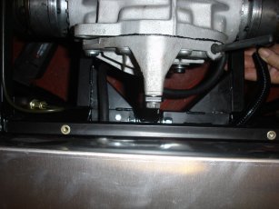
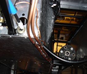
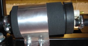 I spent a long time over the past few weeks planning the route of the fuel hoses. I decided after receiving the fuel filter that the pump should fit under the fuel tank, almost in line with the outlet adaptor from the fuel tank. This would mean only about 5 - 6 inches of 1/2" fuel hose would be needed from the tank to the larger inlet on the fuel pump. Then i could route the outlet from the fuel pump up and behind the fuel tank then straight over the chassis rail into the fuel filer inlet. This would minimise the amount of piping needed and give a pretty direct route. As you can see from the pic to the right i needed to wrap foam around most of the pump. This was because the rubber casing for the pump had a protruding ring offset to the left to support the mounting bracket on the right hand side as you see it in the picture. This did not suit my mounting as i wanted the pump to be in the far left of the chassis rail and if the mounting was in the suggested place this would put the mounting bolt holes right in the middle of the differential support bracket. So to enable the mounting bracket to be located at the left of the pump as i wanted it i needed to level the surface of the pump with foam. This worked very well and as you can see from the 2 pics below, enabled me to drill 2 holes right through the chassis allowing me to bolt the M6 bolts all the way through. This is not an easy job as drilling the alloy bracket first then lining up to drill from the underside of the chassis up and then squeezing in the pump and squeezing the bracket together to get the bolts through gave me very sore hands!
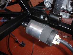
 <11th October 2005>
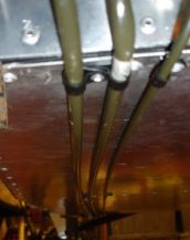
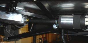
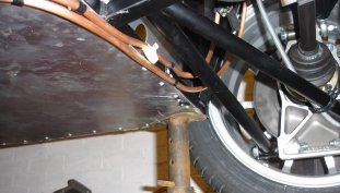
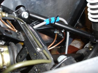
My first job tonight was to use the small pipe bending tool i borrowed from my uncle to put a bend on both the rear ends of the solid fuel pipes. This is so that i can point them inwards slightly to reduce the arch of the rubber fuel pipes a bit to clear the suspension arms. The picture on the left shows the pipes with a rubber pipe attached to the "fuel to engine" solid pipe. I could use this to plan the location of the chassis mountings and the fuel filter
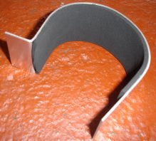
Fitting the fuel filter was exactly the same as the fuel pump. As you can see in the picture below, i lined the bracket with foam to cushion the filter. Then i drilled two mounting holes in both the bracket and the lower chassis rail. Then fitted with bolts exactly the same way as the fuel pump.
Once this was in place i fitted the pipes up after cutting them to length with a Stanley knife. With the paths along the chassis mapped out i placed the fuel tank in its place and marked out the chassis mountings for the hoses. I then drilled and riveted the cable tie brackets to the chassis. I couldn't fully fit all the hoses as i didn't have anywhere near enough Jubilee clips of the small size needed.
<15th October 2005>
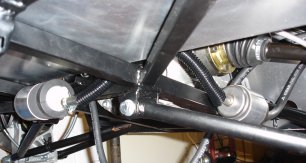
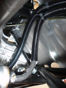
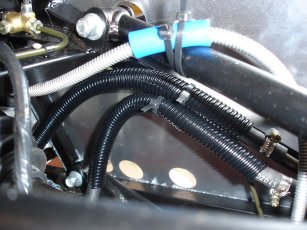
Keith had got hold of some small jubilee clips for me during the week so i secured all the fuel hoses to the fuel pipes, filter, and cable tied them to the riveted chassis mounts. The collection of pics below show you how i fixed them and which paths i took around the chassis.
<18th October 2005>
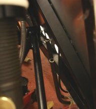
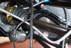
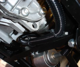
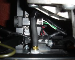
After fitting the wiring loom to the rear of the chassis I placed the fuel tank where it will go to check the clearances. As you can see from the picture below the fuel return hose fits perfectly over the wiring loom and around the Fuel Cut Off switch.
<25th October 2005>
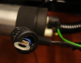
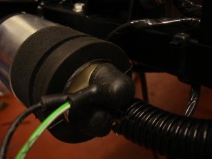
The only job remaining on for the fuelling system is to wire up the fuel pump. This would have been a bit easier with the aid of a crimping tool but after cutting off the supplied slot in connectors i stripped the wires and fitted them into the crimp connection. Using some standard pliers and a screwdriver i managed to get the wires secured in the crimp but i am definitely going to invest in a crimping tool! As you can see in the pictures below these are then bolted onto the pump and there are some rubber covers to keep any water or dirt from the connections.
<13th Decemeber 2005>
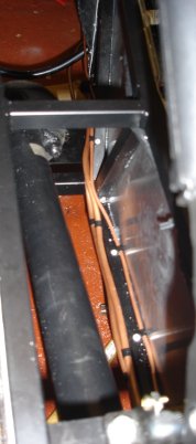
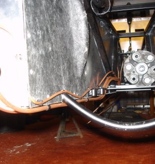
Decided to move the fuel lines from their route under the driver seat today. As i deemed the integrity of the brake pipe to be more important than the fuel line, that took the main chassis rail available. As you can see from the route plan below the fuel lines are marked in red and follow the inside line of the bottom driver side chassis rail.
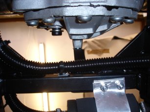
This enables both fuel lines to remain out of the way and protected for the majority of its route. As you can see from the below picture the only real exposure is now just behind the gearbox, before it makes its way into the tunnel.
<20th Decemeber 2005>
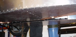
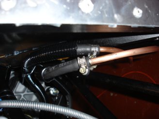
Now the brake pipe is in place i was able to drill out and fit the fuel lines. I decided to change the route slightly to keep slightly more of the brake pipes above bottom and route them above the gearbox mounting plate. As you can see in the pictures below i was able to run both pipes alongside each other on the inside edge of the bottom tunnel rail.
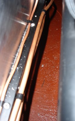
And as you can see from the pics below this has kept them both inside the tunnel for the majority of the body and at the front the gearbox with be lower then the pipes anyway. This has removed the issue of curbs or speed bumps compramising the pipes but will not protect them against stones and the like. I figure it's much better then the original route though!
<7th January 2006>
Finished off the majority of the fuel piping by riviting the pipes in their places. I moved the rear position slightly to keep one of the pipe entirely above the bottom level of the car and the other only goes under for the corner at the rear of the tunnel.

And right next to the gearbox at the front.
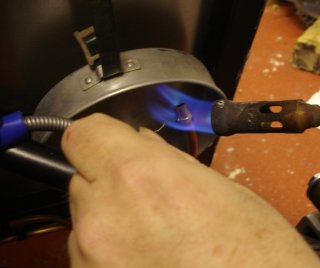
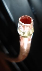 Now i had all the piping in place i had to solder the copper olives onto the ends of the pipe to allow the fuel pipe to go over and lock it down with a jubilee clip. To do this i cleaned the end of the pipe up and rubbed some swarf onto the end, then slipped the olive on. As you can see from the pic on the right it's a pretty tight fit. Then i needed to protect the area i was going to be soldering as i would need to use a blowtorch on the pipe. The only way i could safely do this was to remove the rear right hand suspension and move it out the way. This gave me a clear area except i didn't want to heat up the rear bulkhead panel. So as you can see in the pic below i used a travel saucepan behind the pipe to take the brunt of the blowtorches heat. Then as you can see below i soldered it in place to end up with a nicely fixed copper olive!
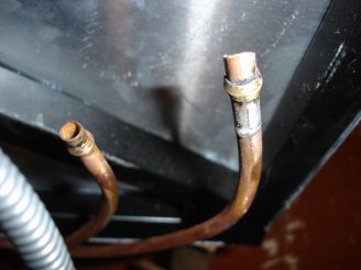
As it turned out the pipe was so tight to get over the copper olive i probably didn't need a jubilee clip but its on now and certainly won't be going anywhere in a hurry! Below is the fully connected pipes at the rear
So with the rear all finished it was just finishing off the front to go. Below are the pics of the pipes rivited down at the front of the tunnel. I haven't trimmed them to size or soldered the olives on to this end yet as i'm waiting to get the throttle bodies and engine in so i can determine where the best place for them to go is.
 Copyright ©2012
Kevin Baldwin
Copyright ©2012
Kevin Baldwin